Gfci Outlet And Switch Wiring Diagram
6 leviton presents how to install a combination device with two single pole switches youtube light switch wiring three way switch leviton. Wiring a gfci outlet and a light switch.
GFCI Switch Outlet Wiring Diagrams
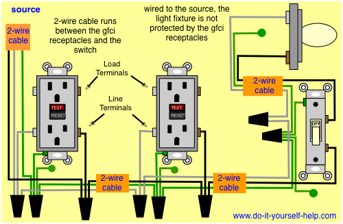
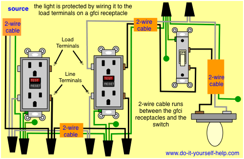
In the first diagram the single way switch and light bulb is connected to the load terminal of gfci.
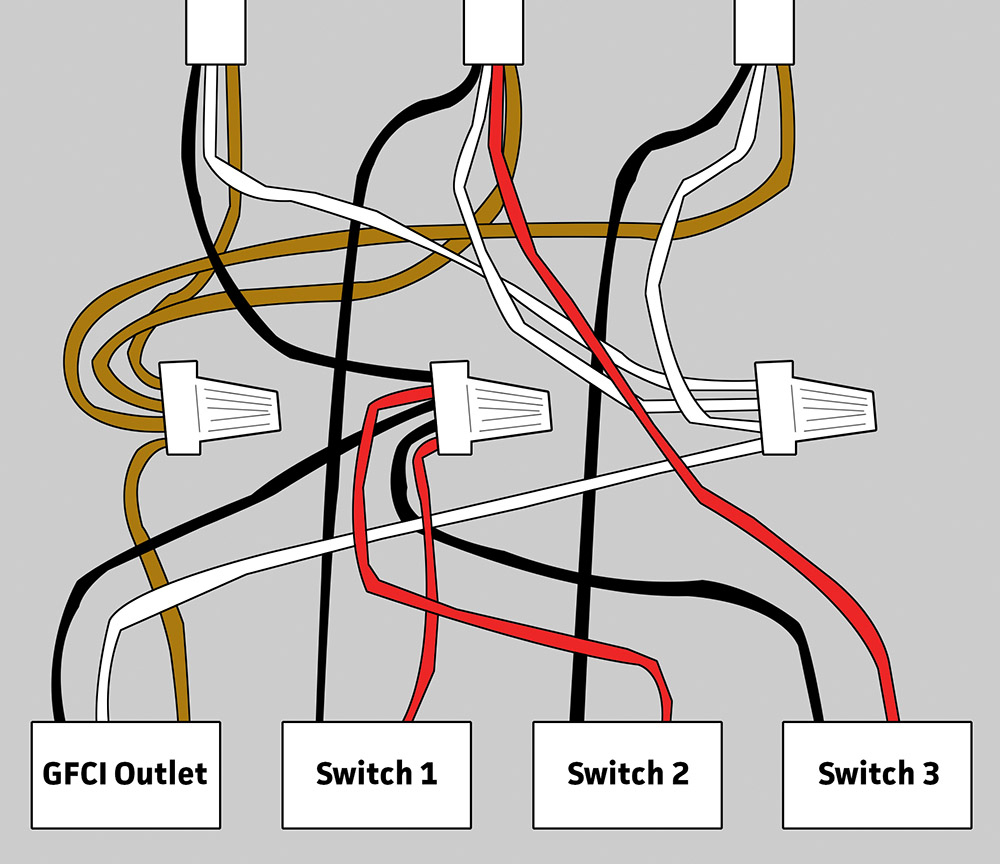
Gfci outlet and switch wiring diagram. Gfci outlet with switch wiring diagram how to install a gfci with 4 wires luxury wiring diagrams for a gfci outlet do. The neutral and ground wires are spliced together and run to each device in the circuit. In the gfci mainly two wires connect as also shown in a diagram the current flowing from the source and coming back are some due to current laws.
Gfci outlet with switch wiring diagram how to install a gfci with 4 wires luxury wiring diagrams for a gfci outlet do. Test the gfci by pressing the black “test” button on the outlet. Otherwise, the arrangement will not function as it should be.
Replace the receptacle screw it back into the box and attach the cover plate. Gfci combo switch and outlet wiring circuit diagrams and installation. Injunction of 2 wires is generally indicated by black dot to the intersection of 2 lines.
Installing a gfci receptacle can be more complicated than installing a conventional receptacle. It means, all the connected loads to the load terminals of gfci are protected. Connect the bare ground wire to the green (ground) screw.
The toggle switch in the combo switch outlet controls the first light bulb while the single way. New wiring diagram ac sharp inverter diagram diagramtemplate diagramsample check more at ht electrical circuit diagram outlet wiring electrical panel wiring. Cover the two single pole light switch device with an outlet cover plate.
The wiring diagrams shown within the instruction sheets provided with the product are for applications in which gfci protection is not required for the circuit connected to the switch. Be a hero and install it right the first time. In this gfci outlet wiring and installation diagram the combo switch outlet spst single way switch and ordinary outlet is connected to the load side of gfci.
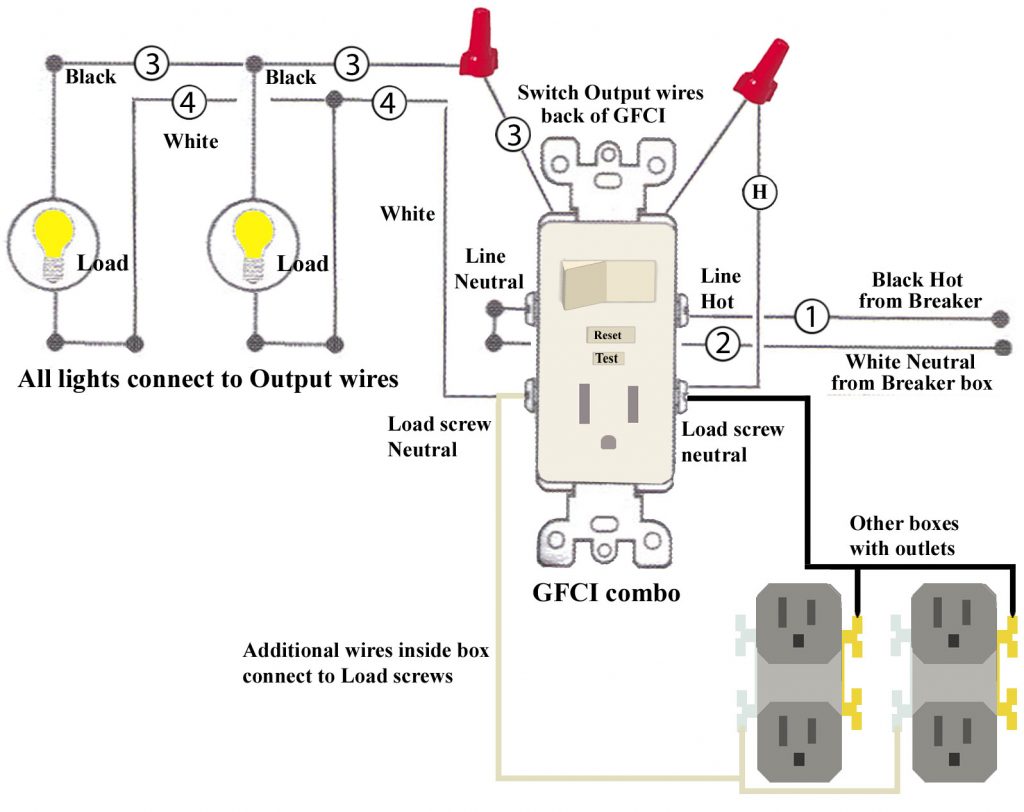
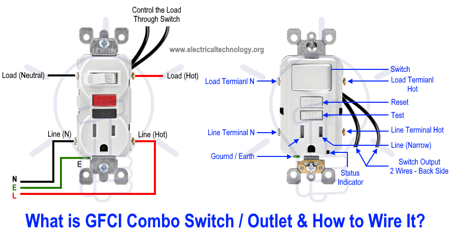
Wiring a gfci combo switch outlet with a light bulb in the first wiring diagram, the connected load (as light bulb) is gfci protected as it is control by the combo switch and connected to the load terminals of gfci. With this kind of an illustrative guide, you are going to have the ability to troubleshoot, avoid, and total your projects easily. The combination gfci/switch’s features 3.
The hot source is spliced to the line terminal on the receptacle and to one terminal on the light switch. Each component should be placed and connected with different parts in specific manner. Wiring a gfci receptacle is a little more complicated than hooking up a regular outlet but easily learned once explained.
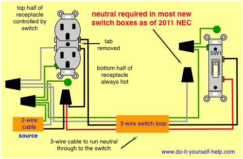
Gfci outlet wiring diagram house electrical wiring diagram. Plug a clock radio or light into the outlet. This diagram illustrates wiring a gfci receptacle and light switch in the same outlet box a common arrangement in a bathroom with limited space.
Switch and outlet wiring diagram gfci outlet wiring leviton. The most common components are capacitor resistorbattery. Ground connection diagram is shown separately.
In this gfci outlet wiring and installation diagram, the combo (switch + outlet), spst (single way) switch and ordinary outlet is connected to the load side of gfci. And again, these switches are located in the middle of a circuit. The leviton combination gfci/switch can be used in a variety of applications, with some requiring gfci protection on the circuit connected to the switch.
An electrician explains how to wire a switched half hot outlet dengarden. However, it does not imply link between the cables. Leviton single pole and 3 way switch installation instructions pdf manualslib.
Wiring diagrams for a gfci and switch combo gfci outlet wiring home electrical wiring. The black wire connects to the gfci hot lead. In the second wiring diagram, the lamp is connected directly to the line terminals of gfci (i.e.
There will be primary lines which are represented by l1, l2, l3, and so on. Angelo on august 12, 2021. This gfci wiring method may be found in a bathroom or kitchen where the switch may be near a water source.
This diagram illustrates wiring a gfci receptacle and light switch in the same outlet box, a common arrangement in a bathroom with limited space. ( see diagram a ). Gfci outlet with switch wiring diagram gallery.
According to previous, the traces at a gfci outlet with switch wiring diagram represents wires. Gfci switch outlet wiring diagrams do a light off dual function afci leviton gfi combo problems installing how i connect to diagram for 20a with 15 amp smartlockpro combination wire 3 way electrical outlets and switches multiple circuit from seperate html switched half hot upgrading. • understand basic wiring principles and techniques • can interpret wiring diagrams • have circuit wiring experience • are prepared to take a few.
Light switch controls an outlet in the same box. At times, the cables will cross. Replace the receptacle, screw it back into the box, and attach the cover plate.
GFCI Switch Outlet Wiring Diagrams
18 Fantastic Single Gfci Outlet Wiring Diagram Images Tone Tastic

Gfci Outlet Wiring Diagram Wiring Diagram

Wiring Gfci Outlet Diagram Practical Awesome, To Wire A Gfci Outlet Diagram 4 Wiring Dolgular
GFCI Switch Outlet Wiring Diagrams

Gfci Electrical Outlet Wiring Diagram WIRGRAM
Gfci Outlet Wiring Diagram Doctor Heck
Wiring Diagrams for GFCI Outlets
8 Popular Gfci To Switch Wiring Diagram Solutions Tone Tastic


Leviton Gfci Receptacle Wiring Diagram Free Wiring Diagram

Gfci Outlet With Switch Wiring Diagram Wiring Diagram

Gfci Outlet with Switch Wiring Diagram Free Wiring Diagram
Wiring Diagrams for GFCI Outlets
How To Install And Troubleshoot Gfci Gfci Outlet With Switch Wiring Diagram Wiring Diagram

Gfci Outlet with Switch Wiring Diagram Free Wiring Diagram
How to Wire GFCI Combo Switch & Outlet? GFCI Switch/Outlet Wiring
GFCI Switch Outlet Wiring Diagrams

electrical How can I wire a GFCI combo switch so that the switch controls the receptacle
Wiring Diagrams for GFCI Outlets